

The parts of an electric fan are built around one set of blades that a motor spins at fixed speeds. Each blade is set at an angle, so the spin pushes air forward in a steady stream.
The fan draws air in behind the blades and expels it in front of them.
Parts of an Electric Fan Labeled Diagram
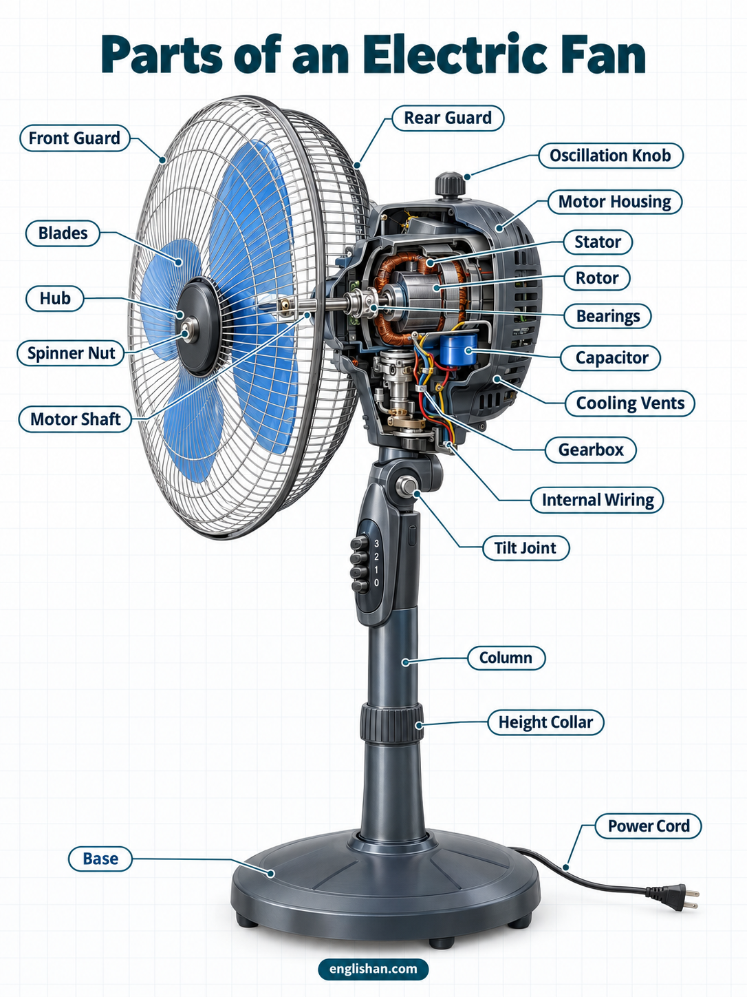
Starting at the front, a fan has a domed front guard, the blades behind it, and a hub at their center. Behind the blades is the motor housing, with a rear guard bolted to its front face and a back cover closing its rear. Under the housing, a tilt joint links the head to a column, and the column rises from a weighted base. Oscillating models add a gearbox on the back of the motor.
| Part | Where you find it |
|---|---|
| 1. Blades | Angled paddles at the front of the motor |
| 2. Hub | Round disc joining the blades to the shaft |
| 3. Spinner nut | Domed nut threaded onto the shaft tip |
| 4. Motor shaft | Steel rod extending from the rotor |
| 5. Front guard | Domed wire cage facing the room |
| 6. Rear guard | Flatter wire cage behind the blades |
| 7. Trim ring | Band clamping the two guards together |
| 8. Center cap | Round cover over the middle of the front guard |
| 9. Motor housing | Molded shell enclosing the motor |
| 10. Back cover | Plate closing the rear of the housing |
| 11. Stator | Fixed ring of copper windings |
| 12. Rotor | Spinning core inside the stator |
| 13. Bearings | Sleeves or balls at both ends of the shaft |
| 14. Capacitor | Small metal or plastic cylinder wired to the windings |
| 15. Cooling vents | Slots molded into the housing |
| 16. Thermal fuse | One-shot safety link inside the windings |
| 17. Internal wiring | Color-coded leads joining switch, capacitor, and windings |
| 18. Gearbox | Small case on the back of the motor |
| 19. Crank arm | Short rod linking the gearbox to the head |
| 20. Oscillation knob | Push-pull knob on top of the housing |
| 21. Tilt joint | Pivot with a hand screw under the housing |
| 22. Speed switch | Buttons or dial on the base or housing |
| 23. Column | Telescoping pole between the base and the head |
| 24. Height collar | Clamp ring where the two tubes overlap |
| 25. Base | Wide plate or cross of feet on the floor |
| 26. Power cord | Cable running from the base to the outlet |
Fan Blade Assembly Parts
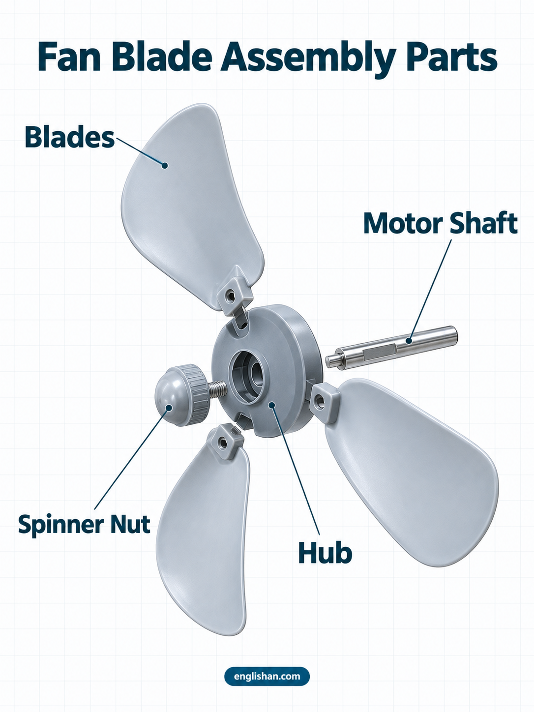
Four of the parts of an electric fan form its front end: the blades, the hub, the spinner nut, and the motor shaft. This is the only exposed moving unit, and the span of the blades gives a fan its size.
Blades
A household fan has three or five blades of plastic or stamped aluminum, each a curved paddle set at an angle to its path. Plastic blades are molded, while aluminum blades are stamped from sheet and riveted to a metal hub. A 16-inch fan measures 16 inches across the blade tips.
Hub
At the center of the blades is a round disc called the hub, made of molded plastic or cast metal. Its bore is a round hole with one flat side that matches the flat on the motor shaft. The blades attach to its rim, and the spinner nut closes its front face.
Spinner Nut
A small domed cap of plastic or metal forms the spinner nut, in the middle of the hub at the front of the blade assembly. It threads onto the tip of the motor shaft. Some fans use a reverse thread, so the nut loosens clockwise, and an arrow molded into the cap shows the direction. The front guard covers the nut completely.
Motor Shaft
A polished steel rod called the motor shaft extends from the front of the motor housing to the hub. A flat is ground into its tip to match the hub bore. Its rear end passes through the motor to the back cover, where the worm gear of an oscillating fan is mounted.
Fan Guard Parts
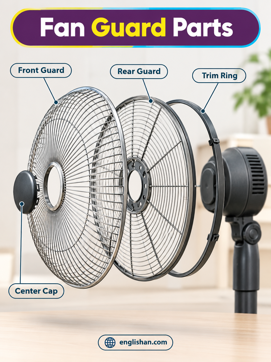
Two wire cages, the outermost of the parts of an electric fan, enclose the blades. The front guard faces the room, the rear guard faces the motor, and the two match in diameter.
Front Guard
Facing the room is the front guard, a domed cage of steel wire. Concentric rings form it, joined by radial spokes that meet at the center. Chrome plating or powder paint coats the wire. Its rim is a heavier ring that mates with the rim of the rear guard.
Rear Guard
Between the blades and the motor housing is the rear guard, a flatter cage of the same wire. Its center is a stamped metal or plastic ring bolted to the front of the housing. Because the fan draws air through it, dust collects on its wires first.
Trim Ring
Around the rim, where the two guards meet, a narrow plastic or metal band forms the trim ring. A small screw or spring clip at the bottom closes it. Loosening that fastener frees the front guard and exposes the blades.
Center Cap
A round plastic disc over the middle of the front guard, where the spokes meet, forms the center cap. Two or three tabs snap it in place, and the brand mark is molded or printed on its face. Behind the cap, the spinner nut stays covered.
Electric Fan Motor Parts
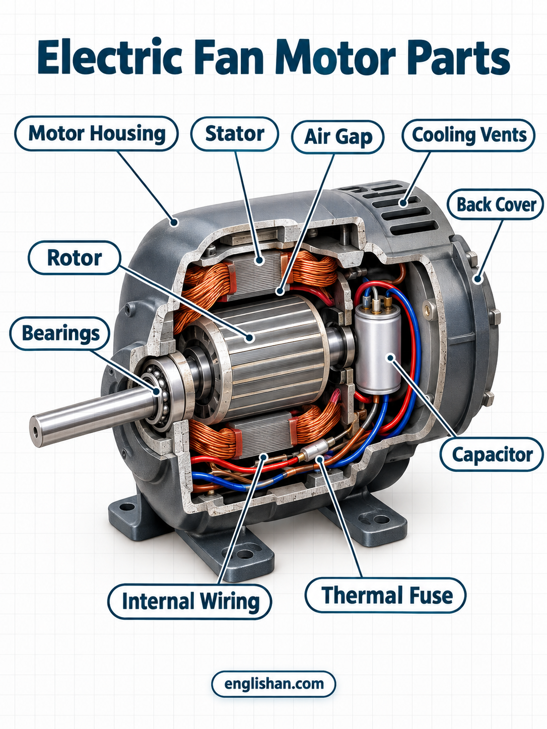
The motor is the heaviest of the parts of an electric fan, a squat cylinder directly behind the rear guard. Everything in this group is enclosed in its housing.
Motor Housing
Directly behind the rear guard, the motor housing is a molded shell of plastic or die-cast metal, round or barrel-shaped. It splits into two halves that are held together by long screws. Vent slots run along its sides, and the tilt joint mounts on its underside.
Back Cover
Screws around its edge hold the back cover, a molded plate that closes the rear of the motor housing. It seats the rear bearing and, on oscillating models, holds the gearbox mount. Removing the cover exposes the rotor and the rear bearing.
Stator
Inside the housing, around the rotor, the stator is a fixed ring of stacked iron plates wound with copper wire. Insulating varnish coats the copper, so the windings show as reddish coils. Bolts through the iron ring fasten it to the housing frame.
Rotor
Mounted on the motor shaft inside the stator, the rotor is a cylinder of aluminum bars set in an iron core. A narrow air gap separates it from the stator. This design is called a squirrel-cage rotor, and its surface looks like a smooth gray drum.
Bearings
One bearing is fitted at each end of the motor shaft, seated in the front of the housing and in the back cover. Budget fans use sleeve bearings, which are oiled bronze bushings with a smooth bore. Premium fans use sealed ball bearings, which are steel rings with a set of steel balls between them.
Capacitor
Fastened inside the housing, the capacitor is a small metal or plastic cylinder about the size of a AA battery. Two wire leads connect it to one winding of the motor, and a printed label gives its rating in microfarads. Its job is to give the rotor a starting push.
Cooling Vents
Narrow slots molded through the sides of the motor housing, in rows near the rear, form the cooling vents. Air passes through them and over the windings. Dust packs the slots over the years, and a soft brush clears them.
Thermal Fuse
Among the parts of an electric fan, the thermal fuse is the one built to fail once. It is a tiny metal cylinder wired in series with the windings and taped beneath their insulation. When the windings overheat, it melts and breaks the circuit for good.
Internal Wiring
A bundle of thin insulated copper leads, color-coded by speed tap, forms the internal wiring. The leads run from the speed switch to the capacitor and the windings. Crimped or soldered connectors join them, and heat-shrink sleeves cover the joints.
Oscillating Fan Parts
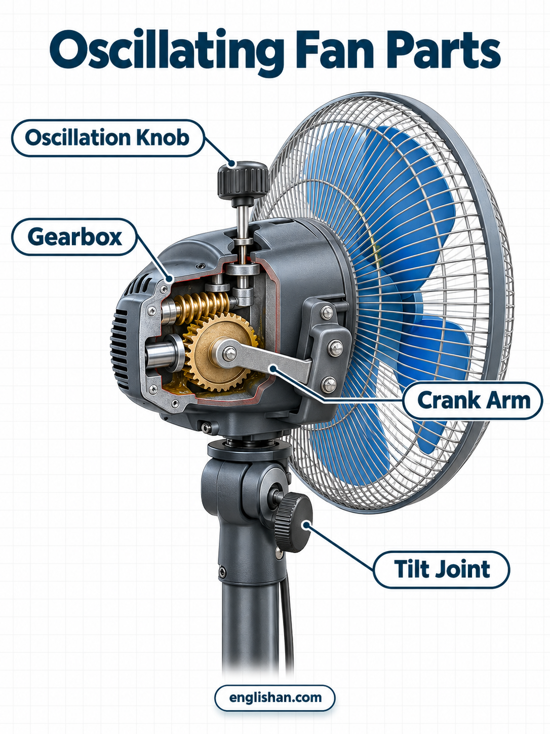
Oscillating models add one more group to the parts of an electric fan. A gearbox, a crank arm, and a control knob are mounted on the back and top of the motor housing.
Gearbox
Bolted to the back of the motor, the gearbox is a small plastic or die-cast metal case. Inside it, a small worm gear on the rear end of the shaft meshes with a larger gear, and grease coats both.
Crank Arm
A short steel rod with a bend at each end forms the crank arm. One end fits an off-center hole in the large gear, and the other end attaches to a bracket on the rear of the head. Its stroke swings the head through an arc of about 90 degrees.
Oscillation Knob
On top of the motor housing, a push-pull knob of molded plastic, the oscillation knob, joins the gearbox by a short rod. Pulled up, it engages the crank arm, and pushed down, it releases the arm so the head stays aimed forward.
Tilt Joint
Under the motor housing, where the head joins the column, a pivot forms the tilt joint. A hand screw, either a wing knob or a thumbscrew, clamps it. Loosening the screw lets the head tilt up or down, and tightening it locks the angle.
Pedestal Fan Stand and Control Parts
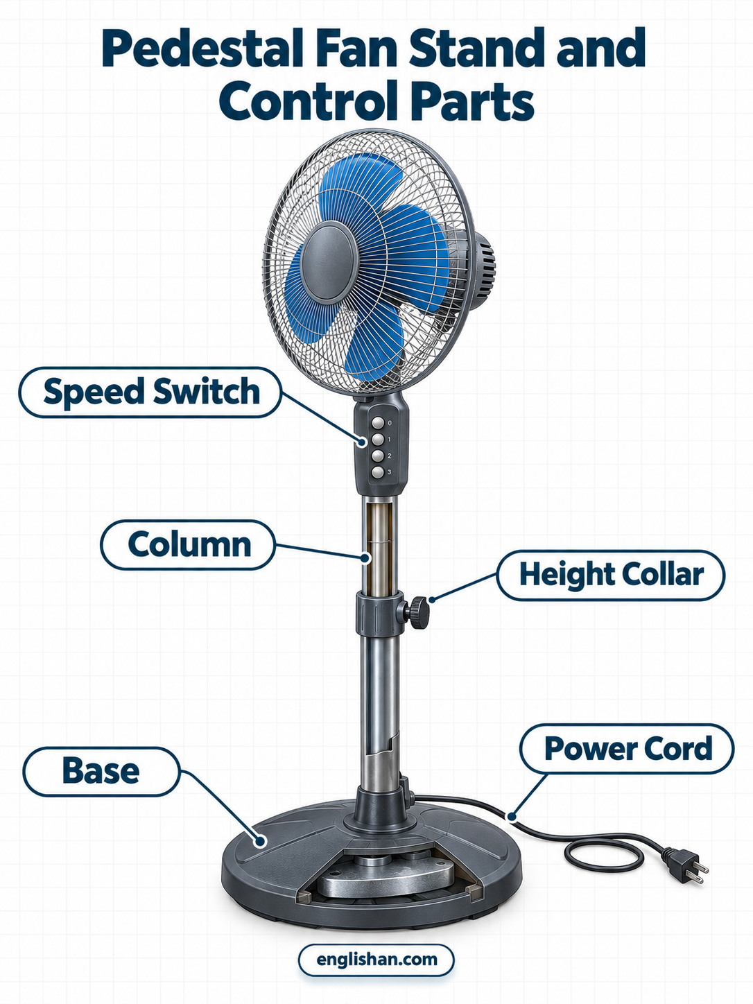
The last group of parts of an electric fan runs from the controls to the floor. It holds the switch, column, collar, base, and cord.
Speed Switch
On the base or the housing, the speed switch is a row of push buttons or a rotary dial. Its positions are labeled low, medium, and high, and some models add an off position and an oscillation button.
Column
On a pedestal model, the column is the tallest of the parts of an electric fan. It is a metal pole that rises from the base to the motor housing. Two nested tubes slide inside each other, so the column adjusts in height, and the motor wires run through its hollow center.
Height Collar
Where the two column tubes overlap, a plastic or metal ring called the height collar circles the column. A screw knob on one side tightens it around the inner tube and locks the chosen height.
Base
At the bottom of the column, the base is a wide round plate or a cross of four feet. Steel or heavy plastic forms it, and a steel plate inside adds weight low down. Its width keeps the fan from tipping while the head swings.
Power Cord
The power cord runs from the base to the wall outlet and is about six feet long on most pedestal fans. A fan draws well under one amp, so the wires inside are thin. The plug has two prongs or three, and hooks molded into the base take up the spare length.
FAQs
Q1. What are the parts of an electric fan and their functions?
The blades push air forward, and the hub and spinner nut fasten them to the motor shaft. The motor spins that shaft, and front and rear guards enclose the blades. A gearbox swings the head, and the column and base hold it up. The speed switch sets the speed, and the power cord feeds the motor.
Q2. What are the internal parts of an electric fan?
The internal parts of an electric fan are the stator, rotor, shaft, bearings, capacitor, thermal fuse, and wiring, all enclosed in the motor housing. The stator surrounds the rotor, and the shaft runs through both. On oscillating models the gearbox and crank arm join them at the back.
Q3. What are the external parts of an electric fan?
The external parts are the blades, hub, spinner nut, and both guards. The oscillation knob, tilt joint, speed switch, column, base, and power cord complete them. All of these are reachable without opening the motor housing.
Q4. What does the capacitor do in a fan?
The capacitor gives the motor its starting push. It shifts the current timing in one winding so the rotor begins to turn, and it steadies the speed once the fan is running. A failed capacitor leaves the motor humming without spinning.
Q5. What are the parts of an electric fan motor?
An electric fan motor has a fixed stator of copper windings and a rotor that turns inside it. A shaft runs through the rotor, and a bearing at each end supports it. The back cover closes the rear of the housing, and the capacitor and thermal fuse are wired to the windings.
Q6. What is the cover of an electric fan called?
The cover over the blades is called the fan guard, and it comes as a front half and a rear half. A trim ring clamps the halves together around the blades. The back cover is a separate plate that closes the rear of the motor housing.
Q7. What are the major parts of an electric fan?
The major parts are the blades, the motor, the guards, and the stand. The blades move the air, and the motor turns them. The guards protect fingers, and the stand sets the height and keeps the fan upright.
You May Also Like