

A centrifugal pump has two ends. The wet end holds the impeller and the casing, which handle the liquid. The mechanical end holds the shaft, sleeve, seal, and bearings, which support and seal the rotating shaft. The parts of a pump follow this split from the suction nozzle to the motor coupling.
Wikipedia names three pump types: positive-displacement, centrifugal, and axial-flow. The names and positions here follow the centrifugal pump, a radial-flow dynamic pump. Reciprocating pumps replace the impeller with a piston or plunger, so their parts are named after the centrifugal parts. Breast pumps, heat pumps, and gas pumps share the name but not the parts.
Parts of a Pump Labeled Diagram
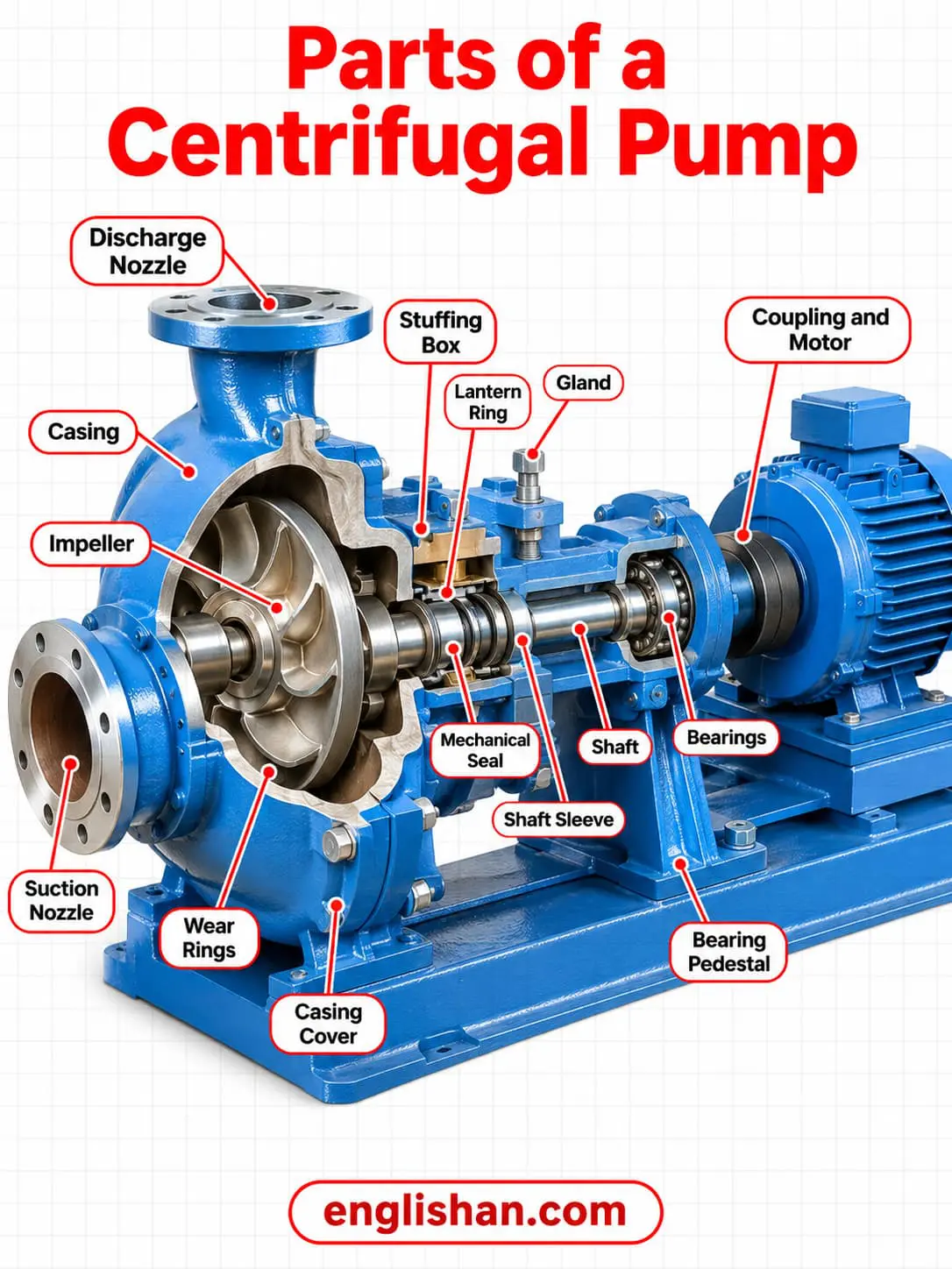
A centrifugal pump has fifteen parts, numbered here from the suction nozzle to the motor. The lantern ring is optional and is used on packed pumps.
| No. | Part | End | Where it is fitted | What it does |
|---|---|---|---|---|
| 1 | Suction nozzle | Wet end | Inlet, with its axis matching the impeller axis | Admits liquid at the impeller center |
| 2 | Impeller | Wet end | Mounted on the shaft inside the casing | Rotates at high speed and imparts velocity to the liquid |
| 3 | Casing | Wet end | Surrounds the impeller | Converts the velocity from the impeller into pressure |
| 4 | Discharge nozzle | Wet end | Outlet, perpendicular to the impeller axis | Releases the pressurized liquid |
| 5 | Casing cover | Wet end | Closes the casing opposite the suction nozzle | Holds the shaft passage and the seal chamber |
| 6 | Wear rings | Wet end | On the impeller, the casing, or both | Keep a small running clearance between impeller and casing |
| 7 | Shaft | Mechanical end | Passes through the casing | Supports the impeller and transmits rotation |
| 8 | Shaft sleeve | Mechanical end | Covers the shaft under the sealing arrangement | Positions the impeller and protects the shaft |
| 9 | Stuffing box | Mechanical end | Where the shaft passes through the casing | Houses the packing or the mechanical seal |
| 10 | Packing or mechanical seal | Mechanical end | In the stuffing box | Seals the gap between the shaft and the stuffing box wall |
| 11 | Gland | Mechanical end | Bolts to the stuffing box face on the casing | Holds the stationary ring of a mechanical seal |
| 12 | Lantern ring | Mechanical end | Near the center of the packing box | Spreads cool liquid around the shaft |
| 13 | Bearings | Mechanical end | Along the shaft | Support the shaft and reduce friction |
| 14 | Bearing pedestal | Mechanical end | Supports the rotating shaft | Also called a block or pillow block |
| 15 | Coupling and motor | Drive | Joins the pump shaft to the driver | Transfers power to the impeller |
Wet End and Mechanical End of a Pump
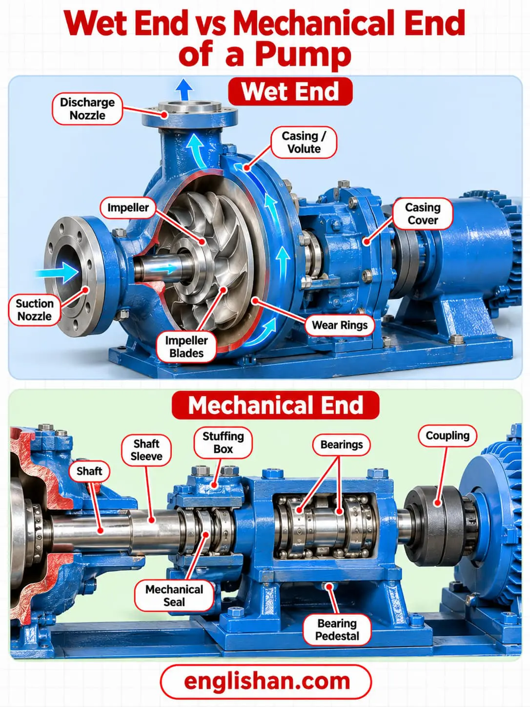
The wet end sets the hydraulic performance of the pump, and the parts of a pump in it are the ones that touch the liquid. The impeller, casing, nozzles, cover, and wear rings are part of it because liquid passes through all of them. The mechanical end gives support, sealing, and rotation, and it holds the shaft, sleeve, seal, and bearings.
Liquid follows one path through the wet end, from the inlet to the outlet.
- Liquid enters through the suction nozzle, whose axis matches the impeller axis.
- It reaches the impeller center, called the eye of the casing.
- The impeller blades whirl the liquid outward through all circumferential parts of the impeller.
- The casing slows the flow and converts kinetic energy into pressure.
- The liquid leaves through the discharge nozzle, which is perpendicular to the impeller axis.
The drive is outside this path. The motor turns the shaft through a coupling, and the shaft turns the impeller.
The pressure gauge is brass or stainless steel.
Parts of a Pump Impeller
Impeller
Among the parts of a pump, the impeller is the rotating part that moves the liquid, mounted on the shaft inside the casing. Its radial blades transfer kinetic energy to the fluid at high speed. PowerZone names steel or stainless steel for industrial-grade impellers and brass, bronze, or plastic for lower-grade pumps. Suspended solids and cavitation worsen impeller wear, according to Wikipedia.
Blades
The blades are the radial vanes that whirl the liquid outward through all circumferential parts of the impeller. Gardner Denver data gives blade counts from 2 to 9, depending on the impeller type.
Hub disc
The hub disc holds the blades. On the channel and vortex types it is angled further back.
Crown disc
The crown disc closes the blades on the closed type. The vortex type and the two-to-four-blade type have none.
Back-of-hub blading
Gardner Denver fits blading on the back of the hub to every impeller it describes. The blading offsets axial thrust and reduces the pressure in the seal chamber. Each of those impellers is dynamically balanced before fitting.
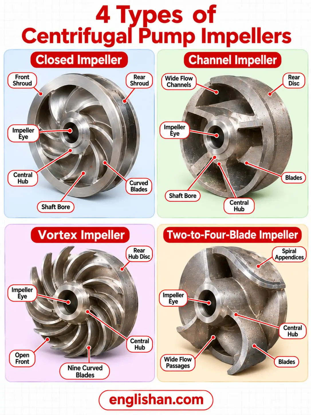
FIRGELLI classes impellers as open, semi-open, or enclosed, and PowerZone calls the closed impeller double shrouded. Gardner Denver data for its pump series separates four designs by blade count and by the liquid each handles.
| Type | Blades | Features |
|---|---|---|
| Closed | 5 to 7 | Suits liquids with few or no impurities, in sizes from 125 mm to 550 mm, with efficiency from 0.6 for the smallest to 0.83 for the largest |
| Channel | 3 to 4 | Wide internal channels pass large solids in wastewater, in sizes from 270 mm to 450 mm, with lower efficiency |
| Vortex | 9 | Has no crown disc and lower efficiency because the liquid is poorly guided |
| Two to four blades | 2 to 4 | Suits dense or viscous liquids, with spiral appendices on two blades reaching toward the suction nozzle and higher efficiency than the channel and vortex types |
Flow direction gives a second split. Axial flow impellers move fluid parallel to the shaft and suit high flow at very low pressure. Radial flow impellers move fluid perpendicular to the shaft and are used in multistage split case pumps. A single suction impeller takes liquid from one side, and a double suction impeller takes it from both sides.
Industrial impellers are steel or stainless steel, and lower-grade impellers are brass, bronze, or plastic. Impeller and casing materials follow the chemical harshness and abrasiveness of the liquid, and the cover uses the casing material.
Volute and Diffuser Casing
Casing
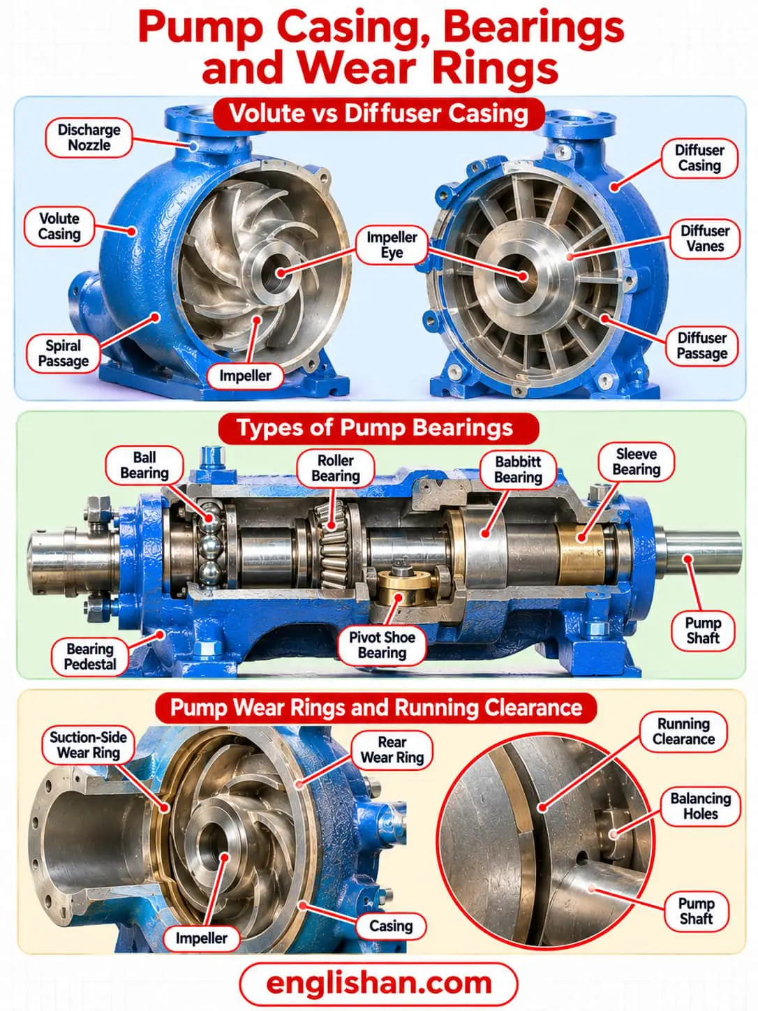
The casing houses and supports the internal parts, helps prevent leakage, and holds pressure in some designs. It converts the velocity energy of the liquid into pressure. Wikipedia names horizontal split casing, vertical joint, single casing, and double casing designs.
Volute
A volute casing is a spiral that collects the liquid at the outer edge of the impeller. Its cross-sectional size grows from zero until it matches the discharge nozzle, which slows the fluid. Gardner Denver offers a narrow spiral and a wide spiral.
Diffuser
A diffuser casing has several vanes that start near the outer edge of the impeller. Wikipedia describes the doughnut-shaped diffuser, or scroll, as the part of the casing that decelerates the flow and increases the pressure.
Casing cover
The cover closes the casing opposite the suction nozzle and holds the shaft passage and the seal chamber. Because of this, the impeller comes out without removing the casing from the pipes. The cover uses the casing material.
Gasket
A flat gasket between the casing and the cover seals the joint, and Gardner Denver builds it free of asbestos. A gasket seals joined parts that do not move against each other.
O-ring
An O-ring closes the gap between surfaces to block liquids and gases. It changes shape under system pressure, and PowerZone places it on static surfaces and round shafts in low-pressure and high-pressure uses.
Suction Eye and Discharge Nozzle
Suction nozzle
The suction nozzle is the inlet and the first of the parts of a pump that the liquid meets. Its axis matches the impeller axis, so liquid enters axially through the eye of the casing at the center of the impeller.
Discharge nozzle
The discharge nozzle is the outlet. It is set perpendicular to the impeller axis, and FIRGELLI describes the outlet as tangential.
Pressure gauge
A pressure gauge measures and displays pressure at the discharge or the inlet. PowerZone names brass and stainless steel as gauge materials.
Wikipedia states that priming is the process of filling the pump with liquid, and that centrifugal pumps need liquid in the casing to prime.
Parts of a Pump Shaft and Sleeve
Shaft
The shaft links the motor to the impeller and transmits rotation to it. Intro to Pumps names steel or stainless steel as the material. Gardner Denver sizes its shafts to limit deflection at the seal, with a critical speed of at least two times the pump speed.
Shaft size
An undersized shaft raises vibration, shortens bearing life, and risks breakage. An oversized shaft adds cost unnecessarily.
Shaft sleeve
The shaft sleeve covers the part of the shaft under the sealing arrangement. It positions the impeller on the shaft and protects the shaft from wear at the seal. Intro to Pumps names bronze or stainless steel as the material, and a sleeve either slides or threads onto the shaft.
The shaft is steel or stainless steel, and the shaft sleeve is bronze or stainless steel.
Parts of a Pump Seal Chamber
Stuffing box
The stuffing box is the annular space around the shaft where the shaft passes through the casing. It is also the seal chamber and holds the materials that control leakage. Gardner Denver offers a cooled version of the seal chamber for water up to 4 bar and a heated version for steam up to 7 bar and 180 °C.
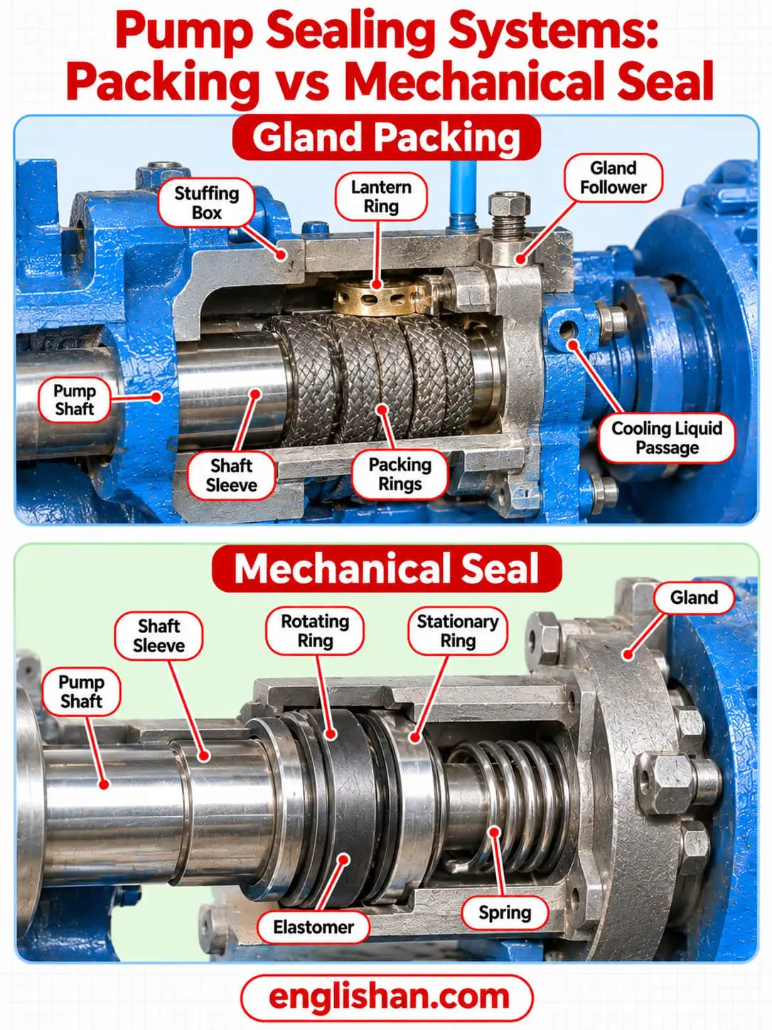
Packing and the mechanical seal are the two sealing arrangements that fit in the stuffing box.
Packing and the Lantern Ring
Packing
Packing is made of braided rings, such as PTFE, compressed around the shaft. Gland packing wraps around the shaft sleeve as rope-like rings. Packed boxes are built for controlled leakage of a few drops per minute, which lubricates and cools the packing.
Gland follower
The gland follower adjusts the compression on the packing.
Lantern ring
The lantern ring is an optional perforated hollow ring near the center of the packing box. It takes cool liquid from the pump discharge or from an outside source and spreads it around the shaft. That liquid cools the shaft and the packing, lubricates the packing, and seals against air leaking in when suction pressure drops under atmospheric.
Packing rings are braided material such as PTFE.
Mechanical Seal Parts
Mechanical seal
A mechanical seal seals the rotating shaft where it exits the pressure chamber, using two smooth faces held together by springs or pump pressure. PowerZone names four categories: single, double, quench, and gas.
Gland
The gland fits around the shaft and bolts to the stuffing box face on the casing. It holds the stationary ring of a mechanical seal.
Stationary ring
The stationary ring, also called the mating ring, is sealed to the gland.
Rotating ring
The rotating ring, also called the primary ring, is sealed to the shaft by an elastomeric part.
Spring
The spring presses the rotating ring against the stationary ring. It bears on a retaining clip or collar fixed to the shaft.
| Feature | Packing | Mechanical seal |
|---|---|---|
| Leakage | Controlled drip of a few drops per minute | Dripless |
| Maintenance | Needs maintenance | Low maintenance |
| Cost | Cost-effective | Costs more |
| Tolerance | Forgiving | Sensitive to misalignment |
Bearings and Bearing Pedestal
Bearings
Among the parts of a pump, the bearings support the rotation of the shaft and reduce friction. Intro to Pumps names standard ball-type anti-friction bearings lubricated with grease or oil. Gardner Denver supports the impeller with two rolling bearings placed outside the casing, sized for a B10 life of 20,000 hours.
Radial bearings
Radial bearings are positioned perpendicular to the shaft and handle radial forces.
Thrust bearings
Thrust bearings are placed parallel to the shaft and counter axial forces. In Gardner Denver pumps the bearing on the coupling side takes the residual axial thrust.
Intro to Pumps calls bearing failure one of the most common causes of pump downtime.
| Bearing | Load handled | Features |
|---|---|---|
| Ball | Radial and axial | Suited to high speeds |
| Roller | Radial and axial | Cylindrical, tapered, or needle rollers |
| Babbitt | Radial, as a sleeve bearing | Sleeve bearing coated with a tin-based or lead-based alloy |
| Sleeve | Radial only | Made of metallic alloys, sintered metals, or plastics |
| Pivot shoe | Axial | Also called tilt shoe or Kingsbury, used as a thrust bearing in high-powered pumps, and needs pressurized lubrication |
Bearing pedestal
The bearing pedestal supports the rotating shaft. It is also called a block or pillow block, and Global Pumps names cast iron or cast steel as its material.
The bearing pedestal is cast iron or cast steel, and sleeve bearings are metallic alloys, sintered metals, or plastics.
Wear Rings and Running Clearance
Wear rings
Wear rings are among the parts of a pump built for replacement, as rings attached to the impeller, the casing, or both. They allow a small running clearance between the impeller and the casing without wearing the impeller or casing itself. Replacing a ring costs less than replacing either of those parts.
Suction side wear rings
Suction side wear rings limit the leakage of liquid from the high-pressure discharge side back to the suction side.
Rear wear rings
Rear wear rings work with balancing holes in the suction eye to lower the pressure behind the impeller, which limits axial thrust.
Clearance affects volumetric efficiency and the load on the thrust bearing.
- Excess suction side clearance increases the flow across the suction side and loses volumetric efficiency.
- Excess rear clearance raises axial thrust enough to damage the thrust bearing.
- Clearance that is too tight risks contact between rotating and stationary parts, which causes catastrophic failure.
Pumps & Systems gives these diametric clearances for new wear rings. Diametric clearance is the difference between the inside diameter of the stationary ring and the outside diameter of the rotating ring, and the running clearance is half of it.
| Ring diameter | New diametric clearance |
|---|---|
| Up to 5 inches | 0.010 inch plus 0.002 inch per inch of diameter |
| 5 to 10 inches | 0.015 inch plus 0.001 inch per inch of diameter |
Some manufacturers recommend replacement when the clearance has grown by 40 percent of the original specified clearance. That figure applies to common water service pumps and mixed-flow impellers.
Parts of a Pump Motor and Coupling
Motor
Crompton names the electric motor as the drive system that transfers power to the impeller.
Coupling
The coupling joins the motor shaft to the pump shaft and transmits power between the two rotating machines. PowerZone names metal discs, rubber inserts, springs, and gears as coupling inserts. Most couplings allow slight angular and parallel misalignment, and some need grease while others run dry.
Two pump designs change the parts at the shaft. Vertical pumps use no stuffing box to seal the shaft, they use a throttle bushing, and their bearings are outside the sump. Magnetically coupled pumps have no direct shaft connection and need no stuffing box or gland, so they use bushings inside the pump.
Reciprocating Pump Parts and Valves
The parts of a pump change when a piston or plunger replaces the impeller. A reciprocating pump is a positive-displacement pump that includes the piston, plunger, and diaphragm designs. The chamber that traps the liquid is a stationary cylinder that contains a piston or plunger. Wikipedia places these pumps where a relatively small quantity of liquid moves at high delivery pressure.
Suction valve
The suction valve is a non-return valve on the suction pipe. It lets liquid flow from the reservoir into the pump and blocks the return.
Delivery valve
The delivery valve is a non-return valve on the discharge side. It builds pressure and protects against backflow.
Cylinder
The cylinder is the hollow, coated part where pressure rises. It holds the piston and the piston rings.
Piston and plunger
The piston moves back and forth on its piston rod to create pressure in the cylinder. A plunger does the same job in a closed, fitted cylinder called a stuffing box.
Crank and connecting rod
The crank joins the power source, and the connecting rod links the crank to the piston rod. Together they convert circular motion into linear motion.
Piston rings and packing
Piston rings and packing seal the piston and limit wear against the cylinder.
Air vessel
The air vessel is an optional part that reduces friction or acceleration head.
Crosshead and wrist pin
PowerZone adds the crosshead, which the wrist pin joins to the connecting rod. The pin oscillates in a wrist pin bushing that is a bearing.
Connecting rod bearings
Also called shell bearings, these bearings support the crankshaft under high-velocity forces.
Pump valves
Reciprocating pumps use valves of disc, abrasion-resistant, wing-guided, spherical, and cage types.
A single-acting pump engages the liquid on one side of the piston, and a syringe is the standard case. A double-acting pump engages both sides, so each stroke both draws in and expels liquid, which takes two inflow pipes and two outflow pipes.
FAQs
The parts of a centrifugal pump are the impeller, casing, suction and discharge nozzles, wear rings, shaft, shaft sleeve, stuffing box, seal, gland, bearings, and bearing pedestal. A coupling joins the shaft to the motor that drives it. Reciprocating pumps use a cylinder, piston or plunger, suction valve, delivery valve, and crank and connecting rod instead.
Intro to Pumps names six common parts: the impeller, the volute or diffuser casing, the shaft, the shaft sleeve, the sealing arrangement, and the bearings. The impeller and casing form the wet end. The shaft, sleeve, seal, and bearings form the mechanical end.
A centrifugal pump has an impeller, a casing with suction and discharge nozzles, a cover, wear rings, a shaft with a sleeve, a stuffing box with a seal, bearings, and a drive. Liquid enters at the impeller center, gains velocity from the blades, and leaves the casing as pressure.
A water pump built on the centrifugal design has an impeller that imparts velocity to the water, a casing that converts it into pressure, a shaft, a shaft sleeve, a seal, and bearings. A motor and coupling supply the rotation. Reciprocating water pumps swap the impeller for a piston or plunger.
Wear rings are designed for replacement, and packing, bearings, and the impeller wear out as well. Packing needs maintenance because it leaks a few drops per minute by design. Bearing failure is one of the most common causes of pump downtime, and impeller wear worsens with suspended solids or cavitation.
The parts depend on the type. A reciprocating positive-displacement pump has a cylinder, a piston or plunger with a piston rod, a suction valve, a delivery valve, piston rings, and a crank and connecting rod. Wikipedia names gear, screw, lobe, vane, and peristaltic designs among the rotary types.
A centrifugal pump has a motor as its drive system, and hand-operated pumps such as a bicycle pump have none. A coupling joins the motor shaft to the pump shaft. Magnetically coupled pumps have no direct shaft connection between the motor and the impeller.
A pump impeller has blades, a hub disc that holds the blades, and a crown disc that closes the blades on the closed type. Blading on the back of the hub offsets axial thrust and lowers the pressure in the seal chamber. Vortex impellers have no crown disc.
A pump coupling joins the pump shaft to the motor shaft and transmits power between them. PowerZone names metal discs, rubber inserts, springs, and gears as coupling inserts. Most couplings allow slight angular and parallel misalignment, and some need grease while others run dry.
Related:
- Parts of a Dishwasher
- Parts of a Refrigerator
- Parts of a Vacuum Cleaner
- Parts of a Ship
- Parts of a Tractor