

The parts of a drill press are the base, the column, the table, the head, the quill, the spindle, and the chuck. The column supports the table and the head, and the motor in the head turns the spindle through a belt.
A drill press holds the bit in a spindle that moves down a fixed vertical line, while the workpiece stays clamped on the table. The parts of a drill are a separate set on the handheld tool, and the parts of a drill bit cover the cutting end. The parts of a bench vice cover the vise that holds work on the table.
Parts of a Drill Press Labeled Diagram
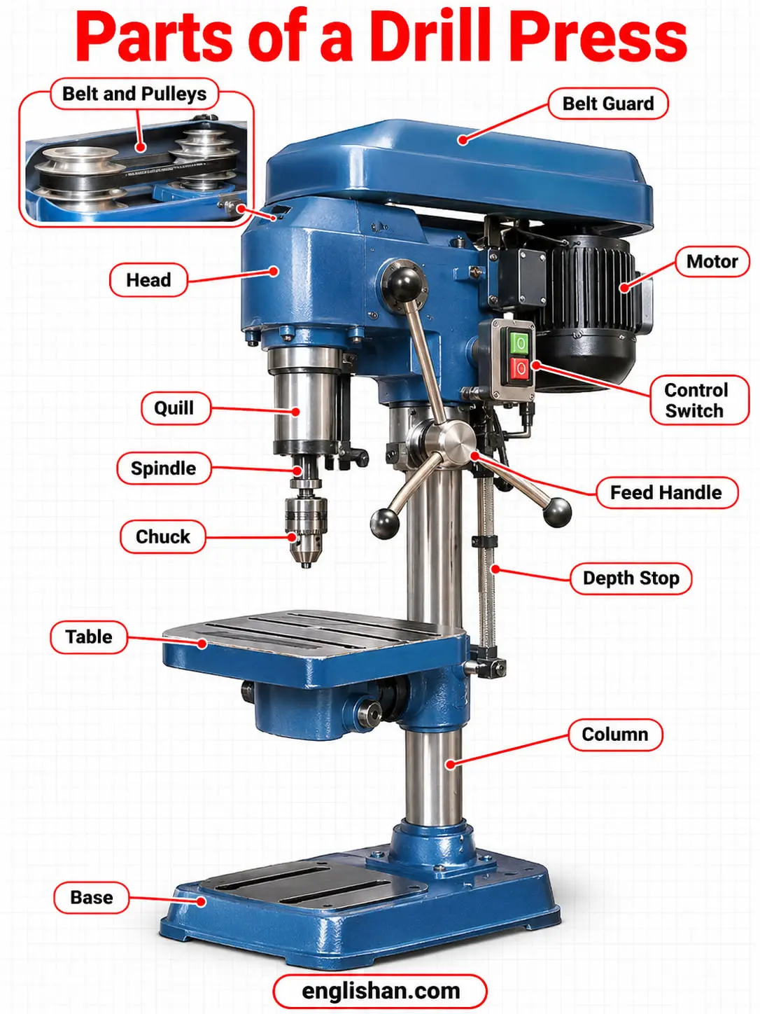
In a labeled diagram of a drill press, the base is at the bottom and the column rises from it. The table slides along the column, the head is mounted on top, and the chuck hangs from the head under the quill.
| Part | Where you find it |
|---|---|
| 1. Base | Foot that rests on a bench, a pedestal, or the floor |
| 2. Column | Vertical shaft mounted on the base, also called the pillar |
| 3. Table | Work support attached to the column |
| 4. Head | Housing on the column that holds the quill, the spindle, and the switches |
| 5. Motor | Power source attached to the head |
| 6. Belt and pulleys | Step pulleys that transmit power from the motor to the spindle |
| 7. Belt guard | Cover over the belt and pulley assembly |
| 8. Quill | Hollow steel sleeve that slides up and down in the head |
| 9. Spindle | Rotating shaft inside the quill |
| 10. Chuck | Three-jaw holder on the spindle for the drill bit |
| 11. Feed handle | Lever that turns the pinion shaft and feeds the quill down |
| 12. Depth stop | Rod that limits how far the quill lowers |
| 13. Control switch | Turns the motor on and off |
Drill Press Base and Column
The base is the foot of the drill press. It is heavy cast iron, and it rests on a workbench, a pedestal, or the floor. A floor-mounted base is heavier and suits large workpieces, while a bench-mounted base is smaller and suits small workpieces.
Bolting the base down dampens vibration, and it stops the press from rocking, since rocking at the base is greatly exaggerated at the top of the machine. Some bases have integrated tee slots for bolting large parts, and the column attaches at the back of the base. Taller workpieces are secured to slots in the base after the table swivels out of the way.
The column, also called the pillar, is the vertical shaft mounted on the base. It supports the table and holds the other parts together. The accuracy of the work depends largely on the column, so it must be sturdy and true. On a radial press, the column holds the radial arm, and the size of the machine is measured from the spindle center to the column.
Parts of a Drill Press Table
The table holds the workpiece, which is clamped in place during drilling. It attaches to the column, and the operator raises or lowers it to match the height of the work. A rack and pinion adjusts the table height on most presses.
A table clamp locks the table to the column at the chosen height. The table also swivels around the column. Slots hold small work, flat edges hold clamps for larger pieces, and a center hole lets the bit pass fully through the workpiece.
Table Tilt
On some models, the table tilts up to 90 degrees for angled holes. A tilt scale and pointer show the angle, and the scale reads 0 degrees when the table is level. An index pin locates the table at exactly 0 degrees, and the pin is removed before tilting.
Most tables are removable. On some large machines, the table is fixed and the head moves instead.
Vise and Clamps
A vise or a clamp holds the workpiece and is clamped to the table. The vise must be moved to drill several holes in the same piece.
Drill Press Head and Quill
The head is the housing mounted on the column. It houses the switches, the gearing, the pulleys, the quill, and the spindle. The quill and the feed handle are on one side of the head, and the motor is on the opposite side, which counterbalances the head.
On some machines, the head moves vertically along the column, and on others, the table moves. On a radial press, the head slides horizontally along the radial arm.
Quill
The quill is a hollow steel sleeve inside the head that holds the rotating spindle. It slides up and down to bring the bit to the workpiece and back, and a spring returns it to the top. The quill does not turn.
The quill handle drives a spur gear. The gear meshes with a rack on the back of the quill and moves it up and down.
Quill Return Spring and Clamp
The return-spring housing is behind the quill and holds the wound spring that returns the quill to the top. Rotating the housing adjusts the spring tension. The quill clamp locks the quill at a set height.
Feed Handle
The feed handle, also called the feed lever or the hand wheel, controls the vertical movement of the bit. It turns a pinion shaft, and the shaft turns the rack and pinion that moves the quill. The pressure on the handle sets how fast the bit meets the workpiece and with how much force.
A hand feed lever has one, two, or three handles. Some machines use automatic feed instead of a handle, or in addition to one.
Depth Stop
The depth stop is an adjustable rod that stops the quill from lowering past a set depth, so every hole reaches the same depth. It comes in two styles: a threaded rod with nuts, and a stop built into the quill handle.
A threaded rod allows fine adjustment by fractions of a turn. The built-in style uses graduated collars with coarser increments, such as 1/16 inch.
Parts of a Drill Press Chuck and Spindle
The spindle is the rotating shaft inside the quill. It turns on bearings in the quill, holds tooling by a Morse taper, and connects to the motor through the belt and the pulleys. The spindle is not designed for lateral forces.
The chuck is the part of a drill press that holds the drill bit. It is mounted on the lower end of the spindle. The chuck has a sleeve, a body, a key, and three self-centering jaws.
A keyed chuck tightens with a chuck key, which gives a slight gear reduction and a gain in torque, so it grips tighter than hand tightening. A keyless chuck tightens by hand, without that gain. A geared chuck on one training machine accepts bit shafts of 6, 9, and 12 millimeters.
Drill Press Motor and Belt Drive
The motor is the power source of the machine, and it is attached to the head. Its size varies with the size of the press, and floor-mounted machines have larger motors. Most models have adjustable speeds from 100 to 3,600 revolutions per minute.
A belt transmits power from the motor to the spindle pulley. Moving the belt to a different step on the step pulleys selects the spindle speed. Some machines use an adjustable pulley to select speed ranges and a variable frequency drive for finer adjustment, and others use a dial-controlled variable speed drive.
The belt is either a flat belt or a V-belt. A V-belt wedges into the pulley grooves tighter and transmits less vibration, but it costs more. Flat belts are common on presses that are not used for sensitive work.
Parts of a Drill Press Guard and Switch
The belt guard covers the whole belt and pulley assembly. A safety shield is a barrier that protects the operator from flying debris.
The control switch turns the motor on and off. Its location varies by model, and it is within reach in an emergency. The emergency stop should be tested before use.
Benchtop and Floor Drill Press Parts
Drill presses differ in size, mounting, and feed, so the parts of a drill press change with the type.
- ✅ Benchtop: Mounts to a workbench.
- ✅ Floor-standing: Mounts to the floor, with a heavier base and a larger motor.
- ✅ Sensitive: The smaller type, on a bench or the floor, where the machinist feels and sees how the drill is cutting.
- ✅ Upright: Like the sensitive type but bigger and stronger, always on the floor, with more controls for the spindle and the table.
- ✅ Radial: Adds a radial arm, which is raised and lowered by an elevating screw, and the head slides along the arm.
- ✅ Magnetic: A mobile drilling machine that is clamped magnetically during use.
- ✅ Numerical control: Controlled by punched tape or a computer, for repetitive, very accurate operations.
Drill Press Part Names
Makers and shops use more than one name for several parts of a drill press. The alternate names come from training texts and parts catalogs.
| Part | Also called |
|---|---|
| Column | Pillar |
| Quill | Sleeve |
| Feed handle | Feed lever, hand wheel, quill handle |
| Depth stop | Quill stop |
| Table | Drilling table |
| Chuck | Drill chuck |
FAQs
The parts of a drill press are the base, the column, the table, the head, the quill, the spindle, and the chuck. The feed handle, the depth stop, the motor, the belt and pulleys, the belt guard, and the control switch complete the machine.
The main parts of a drill press are the base, the column, the table, and the head. The base supports the column, the table holds the work, and the head houses the quill, the spindle, and the switches.
The chuck holds the drill bit. It is mounted on the lower end of the spindle, and its three self-centering jaws close around the shank when the chuck key tightens them.
The quill is a hollow steel sleeve inside the head that holds the spindle. It slides up and down to feed the bit into the work, and a spring returns it to the top. The quill does not turn.
Each part of a drill press has one job. The base and the column support the machine, the table holds the work, the motor and the belt turn the spindle, the chuck holds the bit, and the feed handle lowers the quill. The depth stop limits the travel, and the guard covers the belt.
A sensitive drill press is the smaller type of drill press, and it is mounted on a workbench or on the floor. The machinist feels and sees how the drill is cutting. The upright type is bigger and stronger, and it is always mounted on the floor.
Related: