

Wind turns the blades of a turbine, the blades turn a shaft, and a generator in the nacelle converts that rotation into electricity. The parts of a wind turbine fall into five subsystems: the rotor, the drive train, the electrical system, the control system, and the support structure.
The rotor is the blades and the hub together. The drive train carries torque from the rotor to the generator. A tubular tower holds the whole machine in faster and steadier wind. The order that follows tracks the energy from the blade tip to the grid connection, then covers the vertical axis and offshore designs.
Parts of a Wind Turbine Labeled Diagram
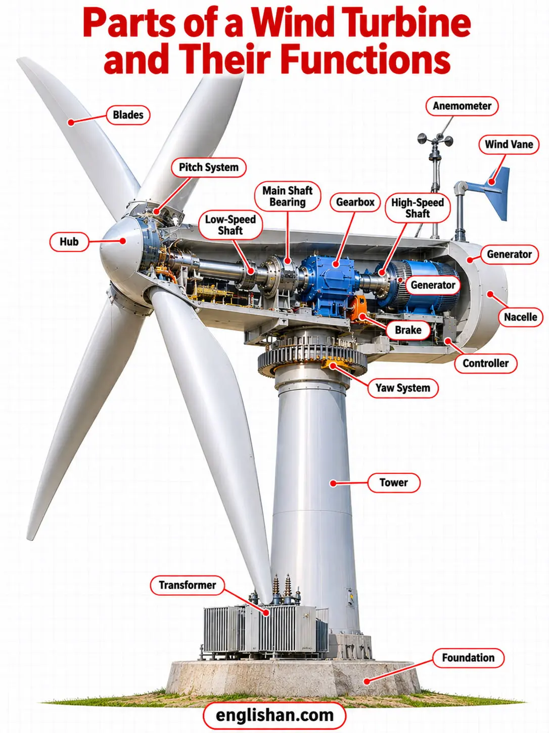
A labeled diagram of a horizontal axis wind turbine shows the rotor at the front of the nacelle, the nacelle on top of the tower, and the foundation carrying the tower. The wind vane sits on the back of the nacelle. The numbered rows follow that layout from the blade tips to the grid.
| Part | Assembly | Function |
|---|---|---|
| 1. Blades | Rotor | Capture wind energy and turn it into rotation |
| 2. Hub | Rotor | Connects the blades to the main shaft |
| 3. Pitch system | Control | Adjusts the blade angle to control rotor speed |
| 4. Low-speed shaft | Drive train | Carries rotor torque at 8 to 20 rpm |
| 5. Main shaft bearing | Drive train | Supports the low-speed shaft and reduces friction |
| 6. Gearbox | Drive train | Raises the rotation speed for the generator |
| 7. High-speed shaft | Drive train | Drives the generator |
| 8. Generator | Electrical | Converts rotation into electricity |
| 9. Brake | Drive train | Holds the rotor still after shutdown |
| 10. Controller | Control | Starts and stops the turbine according to wind speed |
| 11. Yaw system | Control | Rotates the nacelle to face changing wind |
| 12. Wind vane | Control | Measures wind direction and signals the yaw drive |
| 13. Anemometer | Control | Measures wind speed and sends the data to the controller |
| 14. Nacelle | Housing | Encloses the gearbox, shafts, generator, and brake |
| 15. Tower | Support structure | Holds the nacelle and rotor and passes the loads to the foundation |
| 16. Foundation | Support structure | Carries the turbine and its loads |
| 17. Transformer | Electrical | Raises the generator voltage for transmission |
Wind Turbine Blades and Hub
The blades are the longest of the parts of a wind turbine, and most turbines use two or three of them. A three-blade rotor gains about 3 percent in aerodynamic efficiency over a two-blade rotor, which is why utility-scale machines use three. The force of lift on each blade is stronger than drag, and that difference spins the rotor.
Blades
The blades are the outer parts of the rotor, and they capture wind energy and turn it into rotation. Most commercial blades are fiber-reinforced polymers, and glass fiber makes up around 70 percent of the laminate material. Typical land-based blades exceed 52 m (170 ft). Blades last up to 25 years.
Some blades reach a lift-to-drag ratio of 120, compared with 15 for an airliner. In a 60 m blade, carbon fiber is estimated to cut blade mass by 38 percent and cost by 14 percent compared with an all-fiberglass blade. Blade weight limits turbine size because blade mass scales with the cube of the rotor radius.
Blade length has grown with each generation of turbines. The GE Haliade-X blade measures 107 m (351 ft), and the Vestas V236-15.0 MW carries three blades of 115.5 m on a rotor 236 m in diameter.
Hub
The hub is the center of the rotor, and it attaches the blades to the main shaft. Four hub designs exist: rigid, rigid with pitching, teetering, and hinged. In a fixed-blade design the blades bolt directly to the hub, and in an advanced design each blade bolts to a pitch bearing that bolts to the hub.
Pitch System and Yaw System
Pitch system
The pitch system turns each blade about its own axis to control rotor speed, and it feathers the blades in high winds. Hydraulic or electric drives move the blades, and many hydraulic systems are spring-loaded, so the blades furl if hydraulic power fails. Small turbines under 50 kW use centrifugal weights instead of powered pitch.
At wind speeds under the rated speed, the blade pitch stays at the angle that collects the most power. At higher wind speeds the system adjusts the angle to hold output steady. Pitch and yaw are the two control parts of a wind turbine that move in response to the wind.
Yaw system
The yaw system turns the nacelle to face the wind on upwind turbines. Large turbines yaw actively, and the yaw drive takes its signal from the wind vane. The yaw drive has four parts: a yaw motor, a pinion gear, a bull gear, and yaw brakes.
An upwind turbine faces the wind, and most utility-scale land-based turbines are upwind designs. A downwind turbine faces away from it. Downwind and small turbines use free yaw, where aerodynamic loads orient the rotor without a motor. Wind direction varies by as much as 30 degrees at low and medium wind speeds, so active yaw corrects the angle of the rotor continually.
Parts of a Wind Turbine Inside the Nacelle
Nacelle
The nacelle sits on top of the tower and connects the tower to the rotor. Among all the parts of a wind turbine, it holds the most machinery, including the gearbox, the shafts, the generator, and the brake. The nacelle is a lightweight protective cover and not a structural member.
Sensors in the nacelle detect wind speed and direction, and motors turn the nacelle into the wind. The tower and the main frame carry the loads. Large parts such as generators, gearboxes, and blades need an external heavy-lift crane, and a small onboard crane hoists maintenance tools and minor parts.
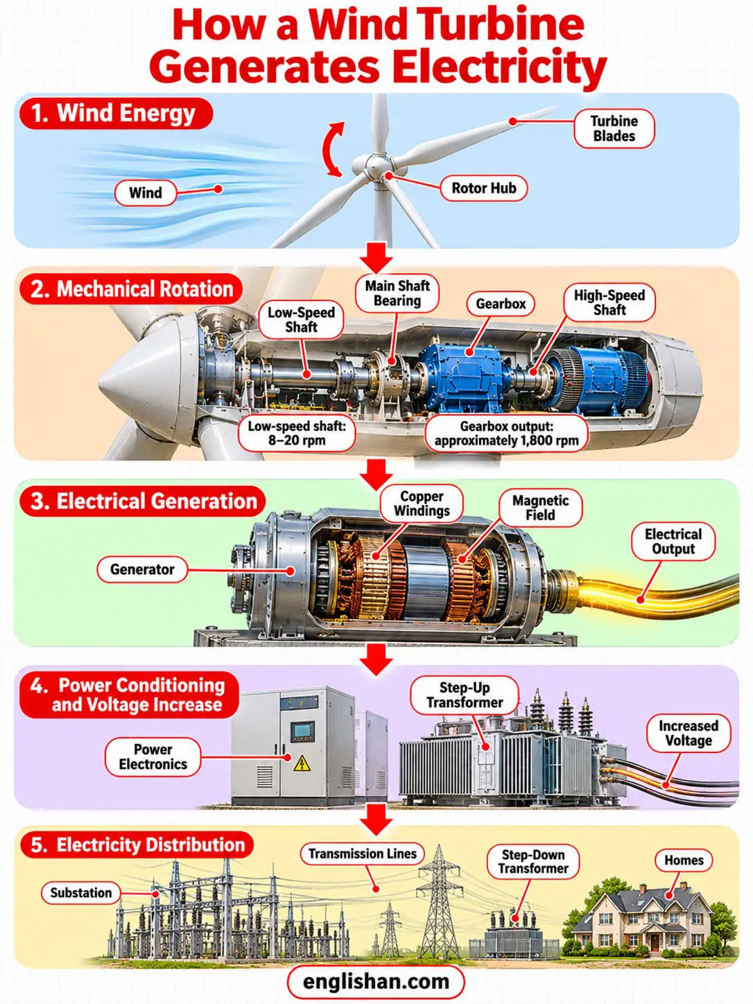
The drive train inside the nacelle transmits torque from the rotor to the generator. Its parts follow one another in a fixed order, and each stage changes the speed of rotation.
| Order | Drive train part | Role and speed |
|---|---|---|
| 1 | Low-speed shaft | Connects to the rotor and turns at 8 to 20 rpm |
| 2 | Main shaft bearing | Supports the shaft and reduces friction |
| 3 | Coupling | Joins the shafts, transmits torque, and dampens torque fluctuations |
| 4 | Gearbox | Raises rotation to about 1,800 rpm, within a range of 750 to 3,600 rpm |
| 5 | High-speed shaft | Drives the generator |
| 6 | Generator | Converts the rotation into electricity |
Low-speed shaft
The low-speed shaft is the first of the drive train parts of a wind turbine, and it connects to the rotor and turns at 8 to 20 rpm. It transfers torque from the rotor to the rest of the drive train and supports the weight of the rotor.
Main shaft bearing
The main shaft bearing supports the low-speed shaft and reduces friction. The bearings carry the reaction loads from the shaft to the main frame.
Coupling
A coupling connects two shafts, transmits torque, and dampens torque fluctuations. One coupling sits between the main shaft and the gearbox, and a second sits between the gearbox and the generator.
Gearbox
Among the drive train parts of a wind turbine, the gearbox raises the rotation speed for the generator, from 15 to 20 rpm on a one-megawatt turbine to about 1,800 rpm. Designs use planetary or parallel gears. Gearboxes last up to 25 years, and they are among the more expensive parts to install and maintain.
High-speed shaft
The high-speed shaft connects to the gearbox and drives the generator. It turns at the speed the generator needs, which is about 1,800 rpm.
Gearbox and Direct-Drive Generators
Generator
The generator is the part of a wind turbine that converts rotational energy into electrical energy with magnetic fields. Copper windings turn in a magnetic field, and that motion produces the current. In a large horizontal axis turbine the generator sits in the nacelle behind the rotor hub.
Four generator types are in use: the induction generator, the wound-rotor induction generator, the doubly fed induction generator, and the permanent magnet direct-drive generator. The doubly fed induction generator is the most common type today. It works efficiently over a wider range of wind speeds and reduces the power spikes that gusts cause.
Doubly fed induction generators and full converters match the variable generator output to the grid frequency. Most generators produce low voltage at 660 V, and some offshore turbines use 3.3 kV medium voltage.
A direct-drive turbine removes the gearbox. The rotor connects directly to a permanent-magnet generator that turns at the rotor speed of 8 to 20 rpm. The gearbox is susceptible to accumulated fatigue torque loading, and the direct-drive design avoids that failure path.
| Feature | Geared turbine | Direct-drive turbine |
|---|---|---|
| Path of rotation | Low-speed shaft, gearbox, high-speed shaft, generator | Rotor to generator |
| Generator speed | About 1,800 rpm | 8 to 20 rpm |
| Gearbox | Present | None |
| Generator type | Induction or doubly fed induction | Permanent magnet |
Parts of a Wind Turbine Anemometer and Wind Vane
The two sensing parts of a wind turbine are the anemometer and the wind vane. Both feed the control system.
Anemometer
The anemometer measures wind speed and sends the data to the controller. Ice buildup makes anemometer readings inaccurate, so some turbine manufacturers offer low-temperature packages with internal heaters.
Wind vane
The wind vane measures wind direction and sends the yaw drive a signal to rotate the nacelle. On large turbines the wind vane sits on the back of the nacelle.
Controller and Brake
Controller
The controller starts the turbine at a wind speed of about 7 to 11 mph and shuts it off at 55 to 65 mph and over. The control system coordinates the pitch, the yaw, and the generator speed to raise output and prevent damage. Aerodynamic control is the most effective method, using passive stall control or active pitch control.
Brake
The brake is one of the parts of a wind turbine that hold the rotor still, and it stops the rotor in an emergency, for maintenance, or when speed exceeds a set threshold. It also keeps the rotor still after the pitch system has shut the turbine down. Disc brakes are mechanical, electrical, or hydraulic.
A mechanical brake is applied only after blade furling and electrical braking have slowed the rotor, because braking at full speed risks a fire. Rotor locks are the primary holding method during maintenance. Small turbines also brake by dumping generator energy into a resistor bank.
Parts of a Wind Turbine Tower and Foundation
Tower
The tower is the tallest of the parts of a wind turbine. It holds the nacelle and rotor and passes static and dynamic loads to the foundation. Most towers are conical tubular steel, built in three segments, and a tubular tower gives protected access to the nacelle. Tubular steel accounts for 30 to 65 percent of the turbine weight.
Height raises output, and winds at 30 m (about 100 ft) or higher are less turbulent than winds near the ground. Doubling the tower height raises the expected wind speed by about 10 percent and the power by about 34 percent. A 3 MW turbine raised from 80 m to 125 m was estimated to increase output from 5,000 MWh to 7,700 MWh per year. Smaller turbines use guy lines to hold the tower.
| Tower type | Material and use |
|---|---|
| Tubular tower | Galvanized steel, the standard construction |
| Lattice tower | Steel truss structure |
| Hybrid tower | Prestressed concrete combined with steel at heights around 120 m |
| Wooden tower | A 1.5 MW turbine on a 100 m tower in Germany and a 2 MW turbine in Sweden since 2023 |
Foundation
The foundation is the part of a wind turbine that supports the entire machine and its loads. It is built of reinforced concrete, with gravity-based designs onshore. Offshore foundations differ by water depth.
Wind Turbine Transformer and Power Electronics
The electrical parts of a wind turbine start at the generator, which outputs low-voltage power. Each step that follows prepares that power for the grid.
| Step | Part | What happens |
|---|---|---|
| 1 | Generator | Produces low-voltage power, 660 V in most turbines |
| 2 | Power electronics | Convert the output to grid-compatible AC |
| 3 | Transformer | Raises the voltage on site |
| 4 | Substation | Links the wind plant to the transmission lines |
| 5 | Step-down transformer | Lowers the voltage for homes |
Power electronics
Power electronics convert the generator output to grid-compatible AC. Doubly fed induction generators and full converters match the variable output to the grid frequency.
Transformer
The step-up transformer sits on the wind plant site and raises the voltage to a transmission level such as 33 kV, the figure Windmills Tech cites. A higher voltage reduces losses over long distances.
Substation
The substation links transmission and distribution and receives the output of the turbines in the wind plant. It lowers the voltage for consumers.
Step-down transformer
A step-down transformer lowers the voltage for homes.
Parts of a Vertical Axis Wind Turbine
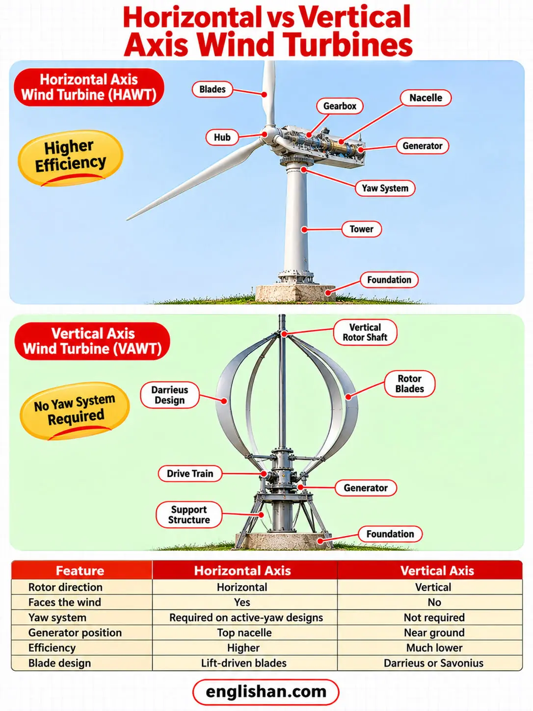
A vertical axis wind turbine does not need to face the wind, so it has no yaw system. That removes one of the parts of a wind turbine in the numbered diagram. The design helps where the wind direction varies, and the vertical layout allows the generator and gearbox to sit near the ground, which makes maintenance easier.
The horizontal axis design is older and more common, and it has the higher efficiency, because a vertical axis turbine produces much less energy over time. The low rotational speed of a vertical axis rotor means higher torque and a costlier drive train.
| Feature | Horizontal axis | Vertical axis |
|---|---|---|
| Faces the wind | Yes, through the yaw system | No yaw system needed |
| Generator position | In the nacelle at the top of the tower | Near the ground |
| Efficiency | Higher | Much lower |
| Blade types | Lift-driven blades on a hub | Darrieus blades or Savonius scoops |
The Darrieus design was patented in the 1920s by Georges Jean Marie Darrieus. It has good efficiency, but it produces large torque ripple and cyclical tower stress that hurts reliability. Three or more blades reduce the ripple. The giromill is a straight-bladed Darrieus subtype.
The Savonius design is a drag-type rotor with two or more scoops, and it starts itself with at least three scoops. Savonius rotors are used in anemometers and some low-efficiency power turbines.
Parts of an Offshore Wind Turbine
The parts of an offshore wind turbine follow the same rotor, nacelle, and tower layout as a land-based turbine. The differences lie in the foundation, the corrosion protection, and the cable connection. Offshore turbines are larger, because installation and grid costs per unit of energy fall with size.
The foundation depends on water depth. Most foundations are monopiles, which are single large-diameter columns. Floating turbines are anchored to the seabed and are technically viable in water 50 to 1,000 m deep.
| Foundation | Water depth |
|---|---|
| Monopile | Up to about 30 m |
| Conventional steel jacket | 20 to 80 m |
| Gravity base | 20 to 80 m, concrete structure for exposed sites |
| Tripod piled | 20 to 80 m, three monopiles joined at the top |
| Floating | 50 to 1,000 m |
Salt water corrosion shapes the design, so offshore towers are tubular steel with cathodic protection and multi-layer coatings. The nacelle is sealed and air-conditioned to control humidity, and the tower is installed in two parts joined by a grouted transition piece.
Subsea cables carry the power ashore. High-voltage AC is the most common connection, but it becomes impractical beyond about 120 km because of cable charging losses. High-voltage DC suits farther sites and needs converters to connect to the onshore AC grid. Crews reach offshore turbines by boat or helicopter.
FAQs
The parts of a wind turbine are the rotor, the nacelle, the tower, and the foundation, plus the controls and the electrical equipment. The rotor is the blades and the hub, and the nacelle holds the gearbox, generator, and brake. The tower carries the nacelle and rotor, and the foundation carries the tower.
The three assemblies that do the core work are the rotor, the nacelle, and the tower. The rotor collects wind energy and turns it into rotation, and the nacelle houses the drive train and the generator. The tower holds both in faster and steadier wind.
The nacelle is the top part of a wind turbine. It sits on the tower and houses the gearbox, the shafts, the generator, and the brake. The rotor connects to the drive train inside it.
The tower is the long vertical part, and it is conical tubular steel on most turbines. The blades are the long rotating parts, and typical land-based blades exceed 52 m. Installations in 2003 used towers of about 65 m. The tallest turbine under construction in Germany as of July 2025 has a 300 m hub height.
The rotor is the part that rotates in front of the nacelle, and it consists of the blades and the hub. The hub connects the blades to the main shaft.
The generator produces the electricity. Copper windings turn in a magnetic field inside the nacelle, and that motion produces the current. The blades and the drive train supply the rotation, and the transformer raises the voltage afterward.
The nacelle holds the gearbox, the low-speed and high-speed shafts, the generator, the brake, the controller, and the sensors. The tower is a hollow tubular steel structure that gives protected access to the nacelle.
No fixed count of the parts of a wind turbine exists, because sources group them differently. National Grid names five parts, and Windmills Tech groups the machine into five subsystems. The U.S. Department of Energy text version labels 16 parts on a geared land-based turbine.
About 85 percent of the materials in a turbine are easily reused or recycled. The blades are the exception, because their fiberglass, carbon fiber, and epoxy composite cannot be remolded. Fiber separation, cement kiln fuel, and construction uses now handle retired blades.
An offshore turbine has the same rotor, nacelle, and tower as a land-based turbine. It adds a monopile, jacket, gravity base, or floating foundation, a grouted transition piece, and subsea cables. The nacelle is sealed and air-conditioned, and the steel carries cathodic protection against salt water.
A vertical axis turbine has no yaw system, because it does not need to face the wind. The vertical design allows the generator and gearbox to sit near the ground. A horizontal axis turbine carries them in the nacelle at the top of the tower.
Related: