


Every light bulb is built from eleven parts, and only three of them show from outside: the glass envelope, the metal screw base, and the filament glowing inside. The other eight are sealed behind that glass or housed in the base.
All eleven parts of a bulb work as a single circuit: current enters at the metal tip underneath, crosses the tungsten coil, and leaves through the screw threads.
Gardeners give the same word to a tulip or garlic bulb, though a plant bulb grows from scales, a tunic, and a basal plate.
What Are the Parts of a Bulb
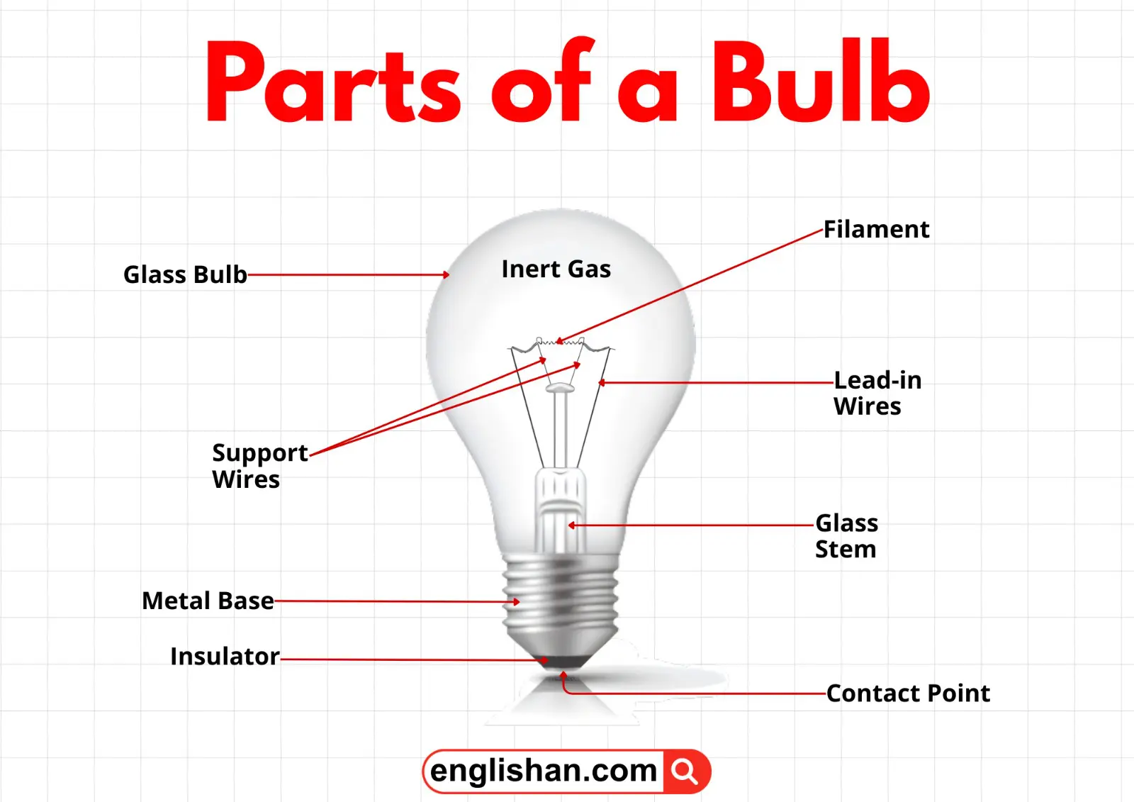
A standard incandescent bulb diagram labels these eleven parts:
- Glass bulb
- Inert gas
- Tungsten filament
- Contact wire to the foot
- Contact wire to the base
- Support wires
- Glass mount
- Base contact wire
- Screw threads
- Insulation
- Electrical foot contact
Six of them stay sealed inside the glass, and five form the base assembly.
Some school worksheets shorten that set to six by merging the two contact wires and treating the whole base as one part. A six-label exercise therefore describes the same bulb more loosely, not a different one.
Parts of a Bulb and Their Functions
| Part | Material | What it does |
|---|---|---|
| Glass bulb | Soda-lime glass | Seals the filament away from oxygen and lets light out |
| Inert gas | Argon and nitrogen | Slows tungsten evaporation so the filament lasts longer |
| Tungsten filament | Tungsten wire | Glows white hot when current meets its resistance |
| Contact wire to the foot | Dumet nickel-iron | Feeds current from the bottom tip to the filament |
| Contact wire to the base | Dumet nickel-iron | Returns current from the filament to the screw shell |
| Support wires | Molybdenum | Steady the filament so it never touches the glass |
| Glass mount | Glass | Seals the wires in place and blocks air leaks |
| Base contact wire | Copper or brass | Joins the internal wiring to the metal screw shell |
| Screw threads | Aluminium | Grip the socket and form one side of the circuit |
| Insulation | Glass or ceramic | Separates the two contacts and prevents a short circuit |
| Electrical foot contact | Brass or solder | Meets the socket spring and admits current |
From the socket, current enters at the foot contact and passes up the first contact wire to the filament. It crosses the coil, then returns down the second wire to the screw threads.
Any break along that path leaves the bulb dark, and the commonest break is at the foot contact itself. Intermittent conduction there shows as flicker whenever the lamp is moved.
Inside Parts of a Bulb
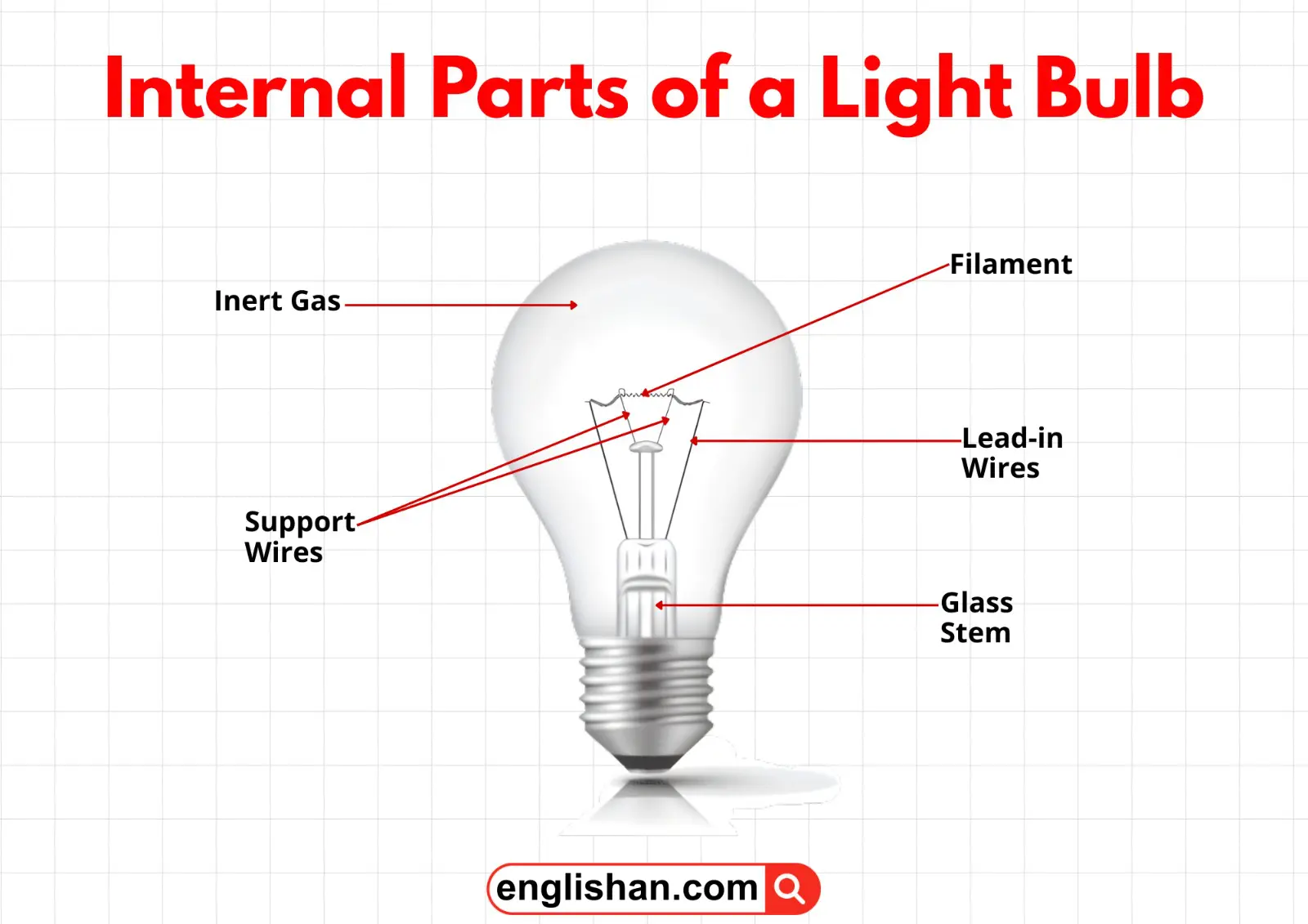
Everything sealed behind the glass either produces the light or protects the wire that produces it.
Tungsten Filament
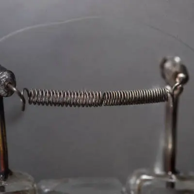
The filament produces light by incandescence: resistance to the current heats the wire until it emits visible radiation.
Few metals survive that treatment, which is why the wire is tungsten, with a melting point of about 3,422 degrees Celsius, the highest of any pure metal. Operating near 2,550 degrees therefore leaves the coil well short of softening.
The same coil is far longer than it looks. Drawn from roughly 2 metres of tungsten wire, a 60 watt filament is wound into a double coil a few centimetres across.
A failed bulb shows the break in that coil against the light.
Support Wires
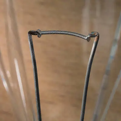
Fine molybdenum wires brace the filament along its length, and they are needed because tungsten loses rigidity at operating temperature. An unsupported coil sags until it touches the glass, which short-circuits the bulb at once.
In a household lamp, two to four of these supports are enough, positioned along the coil where deflection runs greatest. Deflection also explains why mechanical shock shortens service life while the filament is hot.
Contact Wires
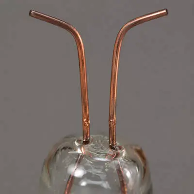
Two contact wires bring current to the filament and take it away again. One reaches down to the foot contact, the other to the metal screw shell, so the pair completes the circuit through the coil between them.
Both are drawn from dumet, a nickel-iron wire coated in copper that expands at nearly the same rate as glass. Matched expansion keeps the seal airtight through thousands of heating cycles.
Glass Mount
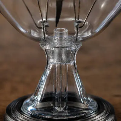
At the neck of the bulb, a flared glass stem fixes the wires in position and seals the envelope against leaks. A crack in that seal ends the bulb at once, because air reaching the hot filament burns it out within seconds.
On a diagram the same stem shows as the pinched glass shape visible through the envelope, labeled as the glass mount, the stem, or the glass support.
Inert Gas
At reduced pressure, a mixture of argon and nitrogen fills the bulb and slows the rate of tungsten evaporation from the hot coil. Evaporated atoms rarely get far.
Each one strikes an argon atom and is redeposited on the filament instead of reaching the glass. Where redeposition fails, tungsten condenses on the envelope as a grey film.
Engineers know that film as bulb-wall blackening, and it develops near the end of the 750 to 1,000 hour service life.
Outside Parts of a Bulb
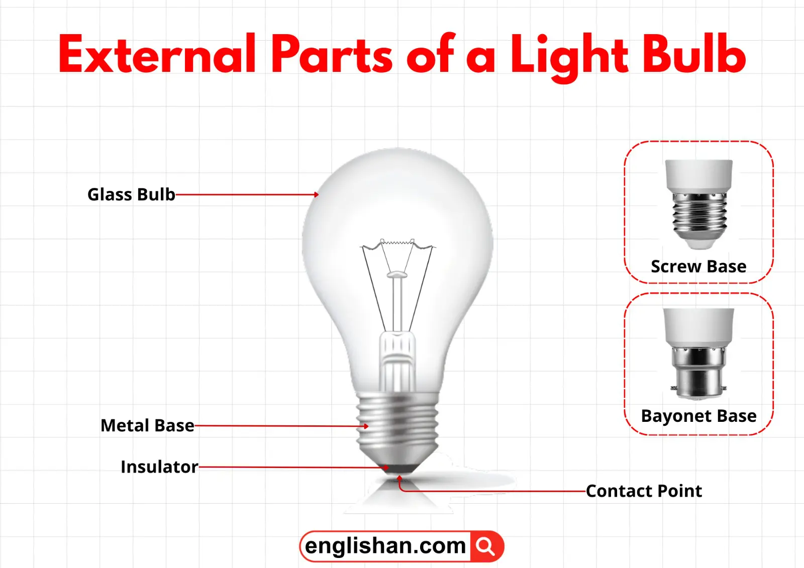
The outer parts protect the sealed interior and connect the filament to the mains supply.
Glass Bulb
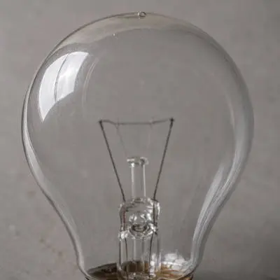
Soda-lime glass, moulded into the familiar pear shape, forms the sealed outer envelope. Its walls exclude oxygen from the filament and transmit the light with almost no loss.
Transmission is deliberately reduced in a frosted bulb, where a fine silica coating on the inside diffuses the output and lowers the glare of the bare coil.
Screw Threads
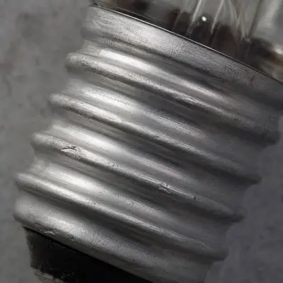
Screw threads grip the socket mechanically and conduct one side of the circuit at the same time. Behind them, the base contact wire solders the internal wiring to the shell.
Shell material changed over time: aluminium replaced the brass and plaster of paris of early bases, because it presses more cheaply and weighs less.
Insulation
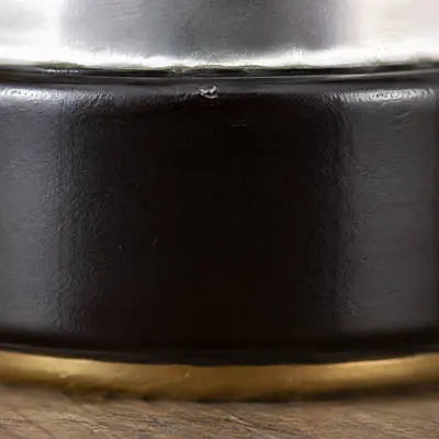
Between the screw shell and the metal tip, a dark glass or ceramic ring keeps the two contacts apart. Separated in this way, they force current through the filament rather than straight across the base.
Scrape that ring away and the bulb short-circuits the moment you switch it on.
Electrical Foot Contact
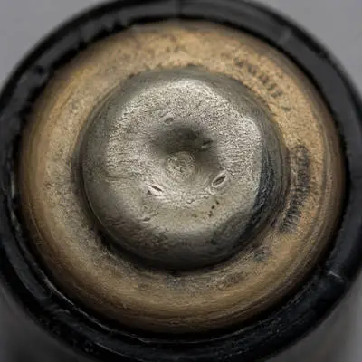
At the very bottom of the base, a small brass or solder button presses against a spring inside the socket. Current enters the bulb at that point, so damage to the button breaks electrical continuity.
A sound bulb will then light in one lamp and not in another.
Which Parts of a Bulb Are Conductors
Seven parts conduct and four insulate.
The conductors are the tungsten filament, both contact wires, the support wires, the base contact wire, the screw threads, and the foot contact, all seven of them metal.
The insulators are the remaining four: the glass bulb, the glass mount, the insulating ring, and the inert gas, all non-metals that block current at household voltage.
- The glass bulb conducts electricity to the filament. ❌ Glass insulates. The two dumet contact wires carry the current, and the glass around them blocks it from escaping sideways.
- The two contact wires conduct electricity to the filament. ✅ Each wire links one end of the filament to one external contact, so current entering at the foot leaves through the threads.
On a battery circuit the foot contact is the positive terminal and the screw shell the negative. Household mains alternates, so neither contact keeps a fixed polarity.
By convention the shell is wired to neutral, so the exposed metal stays at low voltage while you change a bulb.
Light Bulb Base Types
Bulbs are manufactured with several base fittings, and the code stamped on the box matches the socket the bulb enters.
- E26: fits the standard 26 mm screw socket in the United States and Canada.
- E27: measures 27 mm and is the European standard, near enough identical in size to E26.
- E14: threads into the small European sockets on candle lamps, chandeliers, and wall sconces.
- E12: matches E14 in size and is the North American candelabra fitting.
- B22: pushes in and twists a quarter turn to lock, and is common in the United Kingdom, India, and Australia.
- GU10: locks with a twist on a pair of pins, used for ceiling spotlights and track lighting.
- G9 and G4: take small pin-based capsule lamps inside cooker hoods and desk lights.
Read the code on the old bulb before buying a replacement, because the fittings are not interchangeable.
An E14 will not thread into an E27 lamp, and a bayonet cap will not enter a screw socket at all.
The fitting the bulb screws into is the socket, one of the parts of a lamp rather than of the bulb.
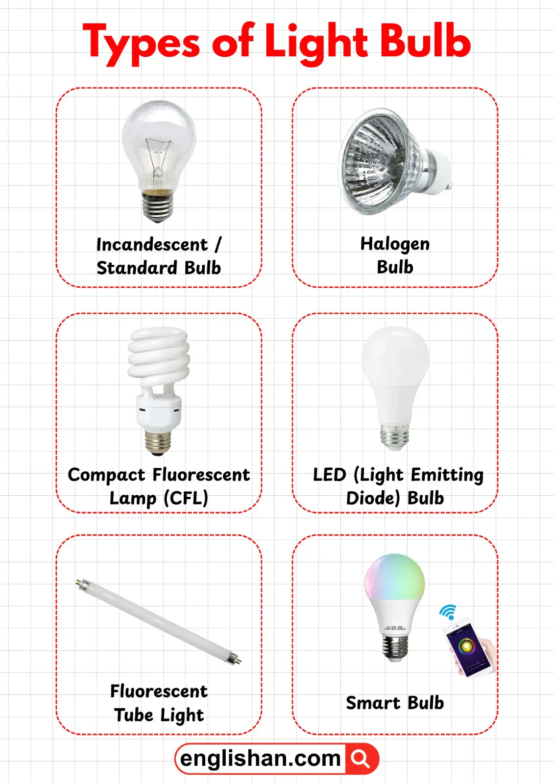
Parts of an LED Bulb
An LED bulb replaces the filament and gas with electronics, so five parts are labeled instead of eleven.
- LED chip: the semiconductor emits light when current crosses it, and several chips are mounted together for household brightness.
- Circuit board and driver: the electronics in the base convert mains alternating current into the low-voltage direct current the chips need.
- Heat sink: the finned aluminium body beneath the dome conducts heat away from the chips, since junction temperature governs how long an LED sustains its output.
- Diffuser: the translucent polycarbonate dome spreads the output of several point sources into even illumination.
- Base: the same screw or bayonet fitting used on an incandescent bulb lets LED lamps retrofit into existing fittings.
Smart bulbs add one part to that set. The addition is a small wireless module beside the driver, which receives Wi-Fi or Bluetooth signals from a phone or speaker.
Parts of a CFL Bulb
A compact fluorescent lamp is built from four parts, and none of them produces light by incandescence.
- Glass tube: a narrow tube is bent into a spiral or a set of U-bends to fit standard fittings.
- Mercury vapour: a trace of mercury inside the tube emits ultraviolet light when current excites it.
- Phosphor coating: the white powder lining the glass converts that ultraviolet light into visible light.
- Ballast: the circuitry inside the plastic base strikes the arc and then regulates the current through the tube.
Fluorescent tube lights are built from the same four parts in a straight tube, with the ballast housed in the ceiling fitting rather than the lamp.
Parts of a Halogen Bulb
A halogen bulb is an incandescent bulb with two parts changed.
A small quartz capsule encloses the filament in place of a soda-lime envelope, because quartz withstands higher pressure and temperature.
Halogen gas fills that capsule, either iodine or bromine, and it combines with evaporated tungsten to return it to the coil. Lighting engineers call that recovery the halogen cycle.
The filament and the base fitting are unchanged, so a halogen lamp runs hotter, delivers higher luminous efficacy, and outlasts the incandescent bulb it replaced.
Parts of an Electric Bulb for Class 6
In school science the same object is named the electric bulb, and exam papers require a shorter labeled set.
In that set the five names are the filament, the glass bulb, the inert gas, the terminals, and the base or cap.
A terminal is any point where a wire connects to the bulb, so the foot contact and the screw shell count as the two terminals.
When you draw an electric bulb for an exam, mark the filament as a coil rather than a straight line. Draw both wires from the filament down to separate terminals, then shade the base to show the screw.
Examiners look for those two separate terminals more than for the accuracy of the outline, since the pair proves you understand the bulb inside a complete circuit.
FAQs
Eleven parts are labeled on a standard incandescent bulb diagram. They are the glass bulb, inert gas, tungsten filament, two contact wires, support wires, glass mount, base contact wire, screw threads, insulation, and the electrical foot contact.
The tungsten filament glows, because electrical resistance heats the coiled wire to about 2,550 degrees Celsius. Metal at that temperature emits white light, and no other part of the bulb produces any.
Seven parts conduct: the tungsten filament, both contact wires, the support wires, the base contact wire, the screw threads, and the foot contact. Every one of them is metal, and together they form the path current follows through the coil and back.
The ring between the screw shell and the metal tip is the part named as the insulator. The glass envelope, the glass mount, and the inert gas block current too, which confines the circuit to the metal path through the filament.
The foot contact at the bottom is the positive terminal on a battery circuit, with the screw shell as the negative. On household mains the current alternates, so no contact keeps a fixed polarity. The shell is wired to neutral instead, which leaves exposed metal at low voltage.
An LED bulb is built from five parts: the LED chip, the circuit board and driver, the heat sink, the diffuser, and the base. The chip emits the light, the driver converts mains power to low-voltage direct current, and the heat sink removes heat from the chip.
The socket, also called the lamp holder, is the fitting that grips the bulb. It forms part of the lamp rather than the bulb, and its shape matches the base code, so an E27 socket accepts an E27 screw base.
You May Also Like